BB24, BB50 series cement kiln tail high temperature fans
| BB24、BB50 series cement kiln tail high temperature fan |
|
BB24 and BB50 series cement kiln tail high-temperature fans are used to treat waste gas in cement rotary kilns and can be used as supporting equipment for cement production lines with a daily output of 300 to 8,000 tons. |
|
Features:
Advanced design, compact structure, convenient installation and debugging, easy disassembly and maintenance, safe and reliable operation, wear resistance, high temperature resistance, high efficiency (both above 81%), low noise, flat performance curve, large flow adjustment range, wide efficient area, etc. It is suitable for use under conditions of high operating temperature, high dust concentration and serious wear. Through continuous improvement of the fan and the application of new processes, new technologies and new materials, its comprehensive performance is in a leading position among similar products in the world. |
I. Parameter:
|
Number |
Output(t/d) |
Flow
(10000m3/h ) |
Pressure(mmH2o) |
Working temperature℃ |
Maximum instantaneous temperature ℃ |
Dust content(g/m2) |
Fan model |
Impeller diameter(mm) |
Rotational speed(r/min) |
Efficiency% |
Required motor power(kw) |
|
1 |
1000 |
23.4 |
760 |
350 |
450 |
100 |
BB24 double suction |
2200 |
1450 |
81.8 |
800 |
|
2 |
1500 |
32 |
800 |
350 |
500 |
100 |
BB24 double suction |
2888 |
960 |
84 |
1000 |
|
3 |
2000 |
36.7 |
820 |
350 |
500 |
100 |
BB24 double suction |
3050 |
960 |
83 |
1200 |
|
48 |
850 |
350 |
500 |
100 |
BB24 double suction |
3222 |
960 |
83.4 |
1600 |
|
4 |
2500 |
60 |
700 |
350 |
450 |
100 |
BB24 double suction |
2694 |
960 |
82.05 |
1659 |
|
52 |
920 |
200 |
450 |
100 |
BB24 double suction |
3350 |
960 |
83.16 |
1795 |
|
5 |
4000 |
78.3 |
836 |
350 |
500 |
100 |
BB24 double suction |
2770 |
1000 |
81.8 |
1120 |
|
84 |
850 |
350 |
500 |
100 |
BB50 double suction |
3211 |
960 |
80.7 |
2800 |
|
6 |
8000 |
70-75 |
750-850 |
280-320 |
450 |
100 |
BB50 double suction |
3350 |
960 |
81.3 |
3800 |
II. Structure:
Composition:1. Host part 2. Auxiliary part
Host part:Chassis/air inlet box, impeller, spindle, air inlet, regulating door, shaft seal, bearings and bearing box, bearing box bracket, hydraulic coupling bracket, motor bracket link, coupling, protective cover and anchor bolt part, casing bracket and other parts.
Auxiliary part:Fluid couplings, electric actuators, coolers, expansion joint motors, thin oil stations, electronic control equipment, measuring instruments, turning mechanisms and other parts.
1. Chassis/air box
The casing/air intake box is made of low-alloy structural steel plates connected with appropriate reinforcements. It has the characteristics of convenient installation, disassembly and maintenance.
2. Chassis bracket
The casing bracket is made of low-alloy structural steel channel steel. The bottom surface matches the foundation foundation. The upper part is connected to the casing/air intake box. The conical spring washer clamped in between acts as a shock absorber. The bracket itself is connected with bolts to facilitate level adjustment.
3. Impeller
The impeller is composed of a backward single-plate blade, a rear disc, an hub plate, a cone disc, a liner, an inlet ring, and a thrust blade. It has the characteristics of good craftsmanship, good wear resistance and high strength.
4.Spindle
The spindle is made of alloy structural steel, forged, and undergoes quenching and tempering treatment and flaw detection inspection. Excessive stress concentration caused by changes in shaft diameter can also be avoided.
5. Adjustment device
The regulating valve of the air intake box is adjusted by differential blades. The blades are streamlined and welded with steel plates. It has the characteristics of advanced structure. The differential blade adjustment gate can be very sensitive to give the fan optimal efficiency under low-speed operation.
6. Turning mechanism
The inner sleeve of the turning mechanism clutch runs synchronously with the rotor main shaft, while the clutch outer sleeve remains stationary. The function is to 1. prevent the spindle from bending due to the weight of the impeller under high temperature conditions, and 2. avoid vibration during restart.
7. Air inlet
The air inlet is made of low-alloy structural steel through stamping. This structure has good gas circulation performance.
8. Fan bearings and bearing boxes
The bearing box structure is simple and has good sealing performance.
9. Bearing box bracket
The bearing box bracket is formed by plate welding, and is connected to the casing bracket with bolts. It is connected to the casing air inlet box using an expansion bracket. The function of the expansion bracket is to control the expansion direction of the casing and the air intake box, and only allows expansion in non-fixed directions.
III. Start the program
1. Turn on the oil pump to allow the oil to circulate through the bearings. After normal operation, start the main motor and adjust the speed through the hydraulic coupling until the fan gradually reaches 2/3 of the rated Rotational speed. Then stabilize it for 15-30 minutes until the temperature of the hydraulic coupling and fan bearings stabilizes, then accelerate the fan to normal operation;
2.During acceleration, attention should be paid to checking the bearing amplitude. If it is out of tolerance, stop immediately for inspection;
3.If the fan delivers cold air, the adjustment should be turned off in order to ensure that the main motor is not overloaded and starts in the shortest time;
4.When the fan reaches full speed, the amplitude, temperature rise and abnormal sound of the fan and motor bearings should be checked one by one;
5. If the fan is stopped for inspection or maintenance, the equipment should be checked to see if there are loose bolts and nuts to avoid harm to the fan.
IV. Precautions during fan operation
1. Establish strict operating regulations;
2.Regular maintenance of bearings requires regular inspection of the oil quality and oil level of the lubricating oil;
3.Change the oil in the bearing box every 6 months and clean it once a year;
4.The oil smell of the hydraulic coupling should also be checked regularly;
5. Regular maintenance instructions should be given to the oil station and hydraulic coupling;
6. Strictly control the inlet and outlet temperatures of cooling water and oil;
7. Strictly control the temperature rise of the bearing box bearings, which should generally not exceed 50°C;
8. Check the bearing amplitude regularly. Under normal circumstances, the maximum amplitude should be less than 100 microns;
9. If the fan blades are worn, the dynamic balance should be re-calibrated after welding repairs;
10. Fans should be inspected regularly according to usage conditions, and generally should be overhauled once a year;
11. Before the fan is operated, the turning mechanism should be filled with grease.
V. Safety protection measures for fans
1. Before starting the fan, rotating parts must not be left without protective devices;
2.The observation door of the fan should be closed;
3.During the maintenance process, special attention should be paid, especially to the impeller, and strict safety measures should be taken to avoid harm to the human body due to accidental starting of the motor or its automatic rotation due to natural ventilation. The following measures should be taken for this purpose:
(1) Cut off power to the motor;
(2) For the fixed-end coupling, the protective cover should be removed, and then the coupling device should be removed to disconnect it;
(3) Tie a rope to the impeller and fix the other end in an easily fixed place to ensure that the impeller and main shaft will not rotate during maintenance.
VI. Fan maintenance
1. Maintenance during operation
(1) Check whether the lubrication system is working properly;
(2) Check whether there is over-vibration in the fan;
(3) Check the tightness of the fixing bolts and connecting bolts.
2.Maintenance while stationary
(1) Impeller
In the early stages of fan operation, if there is an opportunity for comprehensive periodic maintenance, the impeller should be inspected to ensure that the impeller is firmly fixed on the shoulder. The impeller should be kept clean and dust and sludge should be removed regularly. Otherwise, the continuous increase in dust will cause the impeller to lose balance and cause vibration.
The impeller should be inspected and repaired regularly.
Every time the impeller is repaired, it needs to be rebalanced. Before making balance correction, you should check the tightness of the bolts, because these bolts may become loose after the impeller is out of balance after running for a period of time.
(2) Spindle and coupling
The spindle should be kept clean and checked for corrosion, paying special attention to the surface of the spindle where it passes through the casing/intake box seal.
The coupling should be kept in a clean environment, the grease should be replaced regularly, and the tightness of the elastic pin should be checked regularly.
Regularly check the oil level of the hydraulic coupling and check the tightness of the fixing bolts.
(3) Bearing
For high-speed rotating self-lubricating spherical bearings, if assembled properly, basically no maintenance is required.
The most important thing is to regularly check the oil level, especially in the early stages of operation to prevent leakage.
Lubricating oil should be replaced at least once a year, usually twice.
The following points should be noted when inspecting or replacing bearings:
a. cut off the power supply;
b. The oil drain pipe stops flowing lubricant;
c. Close the regulating door;
d. fixed impeller;
e. Remove the protective cover, remove the pin from the coupling, and disengage the connection.
(4) Lubrication system
The following points need to be checked daily:
a. Check the oil level to ensure that the lubricant is at the correct level in the tank;
b. Check whether all oil pumps are working properly;
c. Ensure that the pressure gauge gives the correct reading (increasing readings on the pressure gauge indicate this);
d. Check the temperature of the lubricating oil;
e. Check all valves and adjust appropriately, see lubrication equipment instructions for details.
(5) Chassis/air intake box
Just check the tightness of the fastening bolts of the casing/air intake box.
(6) Adjustment door
Under normal operating conditions, little attention is generally paid to adjusting the door. However, at a convenient time, it is recommended to check the following points:
a. Check the tightness of all bolts;
b. Check blade spindles and bearings for wear;
c. Check the flexibility of adjusting blade rotation.
Note: 1. Do not add grease or lubricating oil to the cast iron bearing on the adjusting door;
2. Please refer to the product manual for the electric actuator for adjusting the door.
(7) Inspection agency
a. The clutch is grease lubricated, and lubrication is the most important maintenance indicator;
b. The reducer does not require frequent maintenance, but the correct oil level must be ensured;
c. Gear couplings do not require frequent repairs and maintenance, but they should be checked at intervals to ensure that the gears are kept lubricated.
(8) Possible faults and their solutions:
|
Fault |
Reason |
Correction |
|
Excessive bearing vibration
|
1. Due to the formation of scale, uneven shedding causes the impeller to be unbalanced.
2. The coupling is not concentric
3. The compression bolt is loose
4. Foundation sinking
5. Shaft bending
6. Unstable foundation
7. Bearing damage |
Clean impeller
Check and realign
Fastening bolts
Check the fan bearings and couplings for adjustment and alignment
Find out the actual situation and make corrections
Reinforcement
Check to see if there is a bearing problem and replace it |
|
Bearing overheating |
1. Insufficient lubrication
2. Insufficient cooling water supply to oil cooler
3. Bearing damage
4. Seal friction |
Check pipelines, instruments, valves and oil quality and make necessary repairs
Check water supply pipeline valve pressure flow and inlet water temperature
replace
Check bearing seals and require readjustment |
|
Mechanical noise |
1. Friction between the impeller and the top of the air inlet
2. Impeller and shaft are loose
3. Friction between bearing and bushing
4. There is foreign matter in the casing
5. The fastening bolts of the motor and coupling are loose. |
Check the radial clearance and adjust the air inlet to ensure that the fan housing and pipes do not bear external loads.
The pipeline does not bear external loads
Check bolts
Check the gap with a feeler gauge and make necessary adjustments and clear them
Check and make necessary tightening |
|
Aerodynamic noise |
1. The connecting bolts are loose
2. The gasket is damaged |
Fastening bolts
Need to be replaced |
|
Fan is not running |
1. The fuse is blown
2. The blades and the air inlet are stuck
3. Power outage |
Check and make necessary adjustments |
 Focus on fan equipment production for 24 years
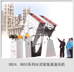


 湘公网安备 43012102000705号